Glance on ansys mechanical supports
Glance on ansys mechanical supports
Introduction:
Dominique Madier and Steffan Evans, two well-known authors of practical FEA books, emphasize that the most critical and challenging aspect of FEA analysis is defining boundary conditions. The reason for this is that an incorrect boundary condition can lead to completely inaccurate results. Therefore, understanding the differences between various types of supports and using postprocessing tools to analyze these differences is a valuable topic to explore in this blog.
Fixed support:
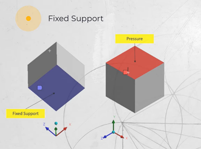
In this support condition, all the degrees of freedom are fixed. The selected support/surface/edge or point is restricted from displacement and rotation. Beams fixed to the walls are shown as one of the great examples of this type of support.
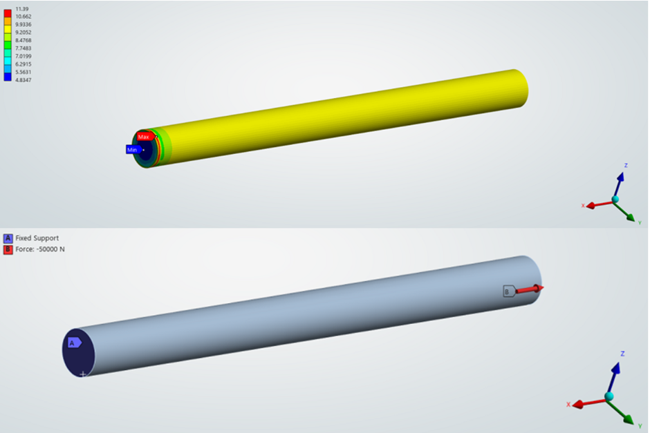
However, make sure that your model is not over-constrained. One of the biggest issues that users often experience is having peak stress points due to being overconstrained. Because your fixed supported surface cannot have any degree of freedom, it is likely to observe local peak stress areas.
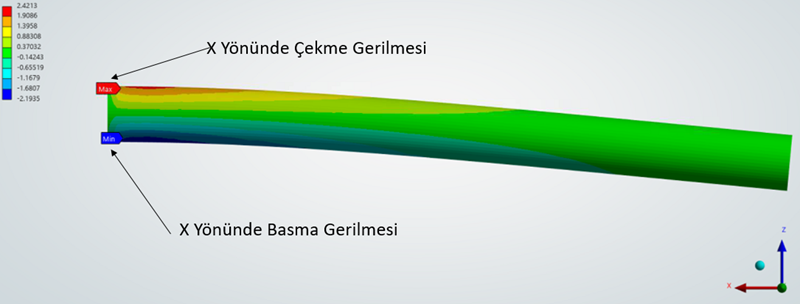
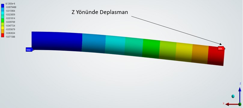
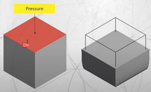
As shown in the figures below, applying a fixed support to a face prevents any deformation due to Poisson’s effect when the surface is subjected to normal pressure or tensile. This restriction can lead to high localized stress concentrations near the support, which may be non-physical or overestimated compared to real-life behavior. In such cases, a other support types can be a more suitable alternatives.
Displacement Support:
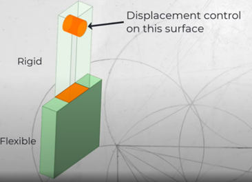
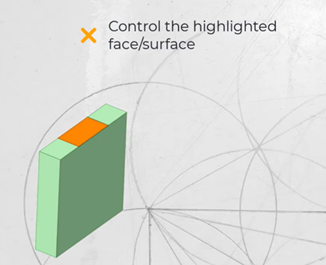
Specify a zero or non-zero displacement to any of three orthogonal directions.
Example: tensile and compression testing
Displacement support specifies a zero or non-zero displacement to any of three orthogonal directions. In other words, you can restrain or give movement to your selected surface/edge/point in any direction (x,y,z). For instance while performing a standard tensile test, test specimens are pulled in a uniaxial direction. This phenomenon can be represented with displacement support.

Frictionless Support:
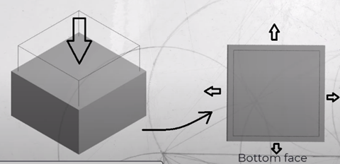
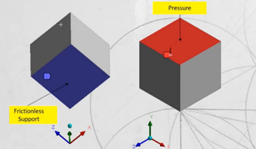
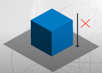
This type of support constrains translational movement in the direction normal to the surface. However, it does not restrict in-plane motion. For instance, let’s think about a cube subjected to pressure in the vertical direction. The cube’s bottom face is subjected to frictionless support, therefore while it restricts the cube’s bottom from moving in the vertical direction, it allows the bottom face to enlarge in-plane direction. It is also applicable in vice versa.
Application:
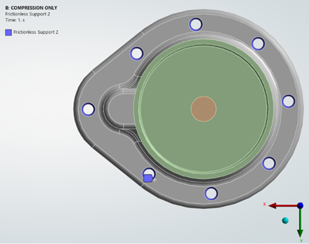

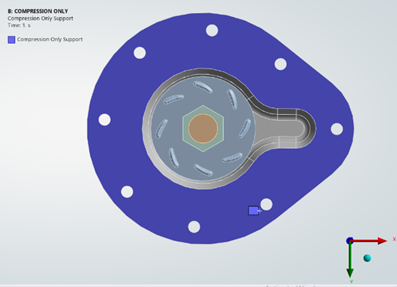
Compression Only Support
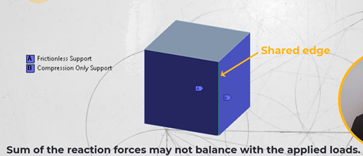
Compression only support allows the surface move in tangential direction, lift off in negative normal direction but cannot move in the positive normal direction.
- Nonlinear support.
- Extra computations.
Application:


Frictionless and compression only supports comparison:
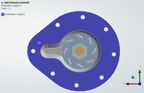
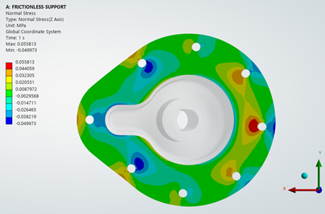
As observed in the figure below, the frictionless support prevented separation in the direction normal to the applied load. This resulted in tensile reaction forces around some of the holes, while compressive reaction forces developed around others due to the asymmetry of the pump housing geometry. On the other hand, the 'compressive-only' support allowed separation in the normal direction of the load, which led to reduced reaction forces and consequently a more evenly distributed tensile stress field.
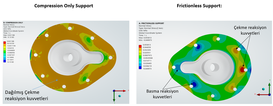
To get accurate balanced forces results, make sure the suppots don’t share edges or nodes.

Cylindrical Support:
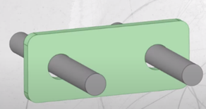
The cylindrical support allows to define a radial clearance over some widths and an axial clearance between two parts. It can be used to model a ring on or in a shaft. The constraint can be rigid or stiffness can be defined.
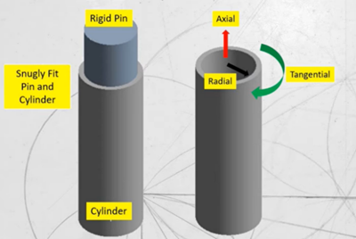
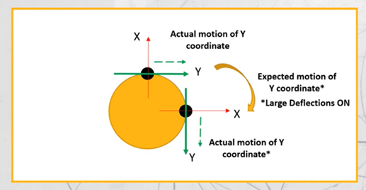
You can also apply cylindrical support to holes. If the shaft is only free to rotate, the tangential force will be free and axial and radial supports will be fixed. However, please be careful cylindrical supports are often valid in small deflections, therefore refrain from using them in large deflection analysis.
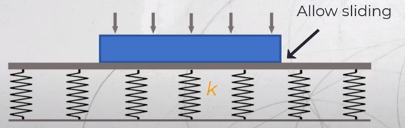
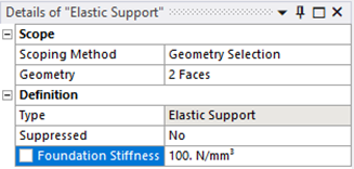
Elastic Support:
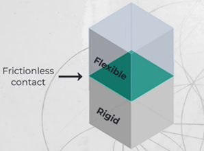
An Elastic Support defines an elastic foundation between the selected faces of a part or assembly and the ground. The Elastic Support is based on a Foundation Stiffness, which is defined as the pressure required to produce a unit normal deflection of the foundation. Elastic Support applies flexible frictionless support to a face.
Elastic support is used to represent foundation stiffness. For example; Elastic support can be used to model piles which are used to support LNG tanks, Another example is base frame or skid are mounted on foundations, which can be model using elastic supports in FEA.
Remote Displacement Support
Remote displacement can be considered one of the most important and practical support types in ansys workbench. In basic terms, it is the easiest way of showing simply supported beams which boundary conditions are that one end is only able to pivot, and the other can both rotate and move in a lateral direction. More general in this boundary condition, you can control both rotations and displacement in the selected axis. This BC contains 6 numbers of degrees of freedom, rotations and displacements in x,y and z.