Advanced Electromagnetic Simulations with Ansys HFSS: A Comprehensive Technical Guide
High-frequency design is at the heart of modern engineering—whether it's 5G communication systems, radar technologies, IoT antennas, high-speed PCBs, or EMC/EMI compliance. Success in these domains depends heavily on accurate electromagnetic modeling, and that’s where Ansys HFSS (High Frequency Structure Simulator) shines.
📌 What is Ansys HFSS?
Ansys HFSS is a 3D full-wave electromagnetic field solver based on the Finite Element Method (FEM). It is specifically developed to solve Maxwell’s equations in the frequency domain with high accuracy. HFSS allows engineers to compute resonance, wave propagation, reflection, delay, impedance matching, and radiation behavior across a broad frequency spectrum.
📐 Mathematical Foundations and Solver Approach
HFSS solves a frequency-domain Helmholtz equation, derived from Maxwell's curl equations in vector form:
∇×(μ−1∇×E⃗)−ω2εE⃗=−jωJ⃗\nabla \times \left( \mu^{-1} \nabla \times \vec{E} \right) - \omega^2 \varepsilon \vec{E} = -j \omega \vec{J}∇×(μ−1∇×E)−ω2εE=−jωJ
Where:
E⃗\vec{E}E is the electric field
ω=2πf\omega = 2\pi fω=2πf is the angular frequency
ε,μ\varepsilon, \muε,μ are the material permittivity and permeability
J⃗\vec{J}J is the current density
HFSS discretizes this equation using curved higher-order tetrahedral elements. Its adaptive meshing algorithm automatically refines critical regions to ensure convergence and accuracy without user intervention.
🧠 HFSS Application Domains
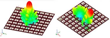
1. Patch Antenna Design
Direct modeling of the substrate and radiating patch.
Supports coaxial probe feed or microstrip line feed.
Outputs include Return Loss (S11), Gain, VSWR, and 3D radiation patterns.
2. Waveguide and Resonator Modeling
Rectangular, circular, and dielectric waveguides.
Supports modal analysis for TE/TM modes.
Accurately identifies resonance frequencies and field patterns.
3. High-Speed PCB and Packaging (3D Layout)
Models detailed PCB structures including vias, pads, power/ground planes.
Enables signal integrity (SI) and power integrity (PI) analysis.
Eye diagrams, TDR, S-parameters for differential and single-ended traces.
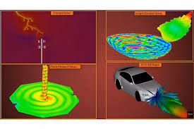
4. EMC/EMI Compliance
Analyze enclosure shielding, cable radiation, filter effectiveness.
Use of Radiation Boundaries and Perfectly Matched Layers (PML) for open-region modeling.
⚙️ Simulation Workflow in HFSS (Advanced Usage)
A. Model Creation
Use HFSS’s built-in 3D CAD tools or import from external formats (STEP, IGES).
For PCB designs, 3D Layout mode supports direct import of ODB++, Gerber, IPC2581 files.
B. Material Definitions
Frequency-dependent dielectric (εr), conductivity (σ), and loss tangent (tanδ).
Supports dispersive, anisotropic, ferrite, and resonator materials.
C. Ports & Boundary Conditions
Supports Wave Port, Lumped Port, Terminal Port.
Boundary options include PEC, PMC, Impedance, Radiation, PML, and Floquet ports.
D. Meshing Strategy
Adaptive refinement based on convergence goals.
Recommended element size ~λ/10 or finer for high-Q applications.
E. Solution Types
Driven Modal (S-parameters)
Eigenmode (resonant frequencies)
Driven Terminal (multi-port full-wave analysis)
Transient Solver (for time-domain radar/switching simulations)
F. Postprocessing
Far-field radiation plots, gain, directivity.
Near-field vector plots (E and H fields).
SAR (Specific Absorption Rate) computation.
Smith Chart and impedance matching analysis.
📊 Example Simulation: 2.45 GHz Rectangular Patch Antenna
📁 Model Parameters:
Substrate: Rogers RO4003, εr = 3.55, tanδ = 0.0027, height = 1.524 mm
Patch Size: 38 mm × 28.8 mm
Feed: 50-ohm coaxial probe
Mesh Density: Min λ/15, with adaptive refinement
📈 Simulation Results:
S11 @ 2.45 GHz: −34.2 dB
VSWR: 1.04
Peak Gain: 7.1 dBi
Radiation Efficiency: 92%
E-plane Radiation Pattern: Omnidirectional, linearly polarized
These results showcase the precision and efficiency of HFSS in antenna design and validation.
🛠️ Automation in HFSS: Parametric Studies & Scripting
HFSS’s Optimetrics module enables automated parameter sweeps, design optimization (gradient-based or genetic algorithms), and sensitivity analysis.
Python or VBScript APIs are available for custom automation:
python
KopyalaDüzenle
oDesign.CreateFrequencySweep( "Setup1", ["NAME:Sweep1", "IsEnabled:=", True, "StartValue:=", "2GHz", "StopValue:=", "3GHz", "StepSize:=", "10MHz"] )
🔄 HFSS Solver Types Comparison
| Solver Type | Description | Use Case |
|---|---|---|
| Modal | S-parameters, impedance matching | Filters, antennas, RF circuits |
| Eigenmode | Resonant frequencies, mode extraction | Cavities, resonators |
| Driven Terminal | Full-wave field analysis with voltage/port feed | Complex passive networks |
| Transient | Time-domain pulse simulations | Radar, signal delay, reflections |
| Hybrid FEM-IE | FEM + Method of Moments | Large open-region models |
🧩 HFSS Integration with Other Ansys Tools
HFSS + Icepak: Coupled electromagnetic-thermal simulations.
HFSS + SIwave: PCB-level signal/power integrity.
HFSS + Mechanical: Multiphysics workflows including FSI.
HFSS + AEDT Optimetrics: Integrated optimization and parametric sweeps.
🔐 EMC/EMI Applications with HFSS
HFSS is a powerful platform for EMC/EMI simulations:
Shielding Effectiveness
Emissions from enclosures or connectors
Crosstalk between transmission lines
Coupling and filtering efficiency
HFSS ensures compliance with EMC standards like CISPR, MIL-STD, and FCC Part 15.
✅ Engineering Takeaways
If your project requires high-fidelity electromagnetic simulation, HFSS is among the best tools in the industry. Key advantages include:
Industry-leading FEM solver accuracy
Automatic adaptive meshing
Powerful postprocessing tools
Seamless integration with Ansys multiphysics platforms
Whether you're designing a patch antenna, analyzing a complex multilayer PCB, or simulating radiation from an RF shielded enclosure—HFSS delivers.
📩 Contact Us for Professional HFSS Services
Need help with HFSS? We provide simulation services, project support, and tailored HFSS training for companies and individuals.